-
Our Location Mumbai, 400004
-
Send Us Mail sales@torrentalloys.com
-
Call Us +91 9920 663 346
Our Location Mumbai, 400004
Send Us Mail sales@torrentalloys.com
Call Us +91 9920 663 346
ASME/ANSI B16.9, ASME B16.28, MSS-SP-43.
1/2 inch (DN 15) to 48 inches (DN 1200).
Seamless, Welded, & ERW.
Schedule 5S, 10S, 20S, S10, S20, S30, STD, 40S, S40, S60, XS, 80S, S80, S100, S120, S140, S160, XXS.
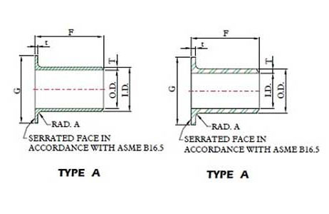
Bevel End, Type A and Type B.
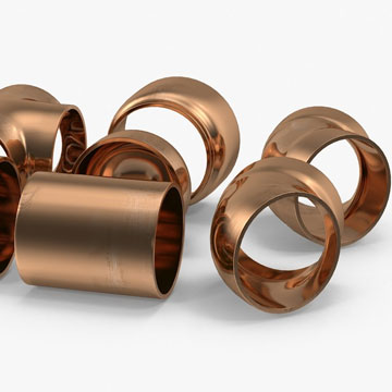
Stainless Steel, Carbon Steel, Alloy Steel, Super Duplex, Duplex Steel, High Nickel Alloys, Copper Nickel.
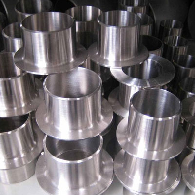
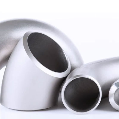
A long stub end is a specialized pipe fitting commonly used in piping systems to connect pipes to flanges, allowing for easy assembly and disassembly. This fitting plays a crucial role in applications where frequent dismantling is required or where thermal expansion and contraction are concerns. long stub ends are essential components in piping systems where flexibility, ease of maintenance, and durability are critical. Their design and material options make them suitable for a wide range of applications across different industries.
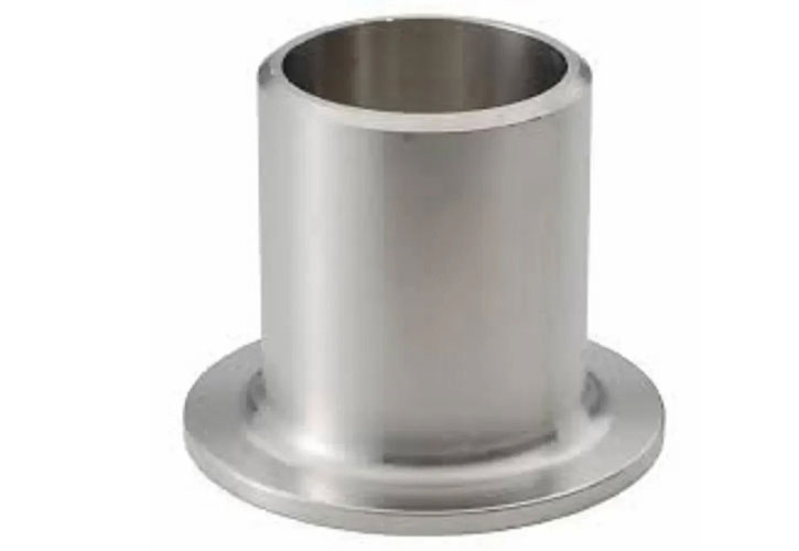
The structure of a long stub end is designed with precision to seamlessly integrate into piping systems, particularly where frequent disassembly or realignment is necessary. The fitting features a cylindrical body that matches the diameter of the pipe it connects to, ensuring a secure and consistent fit. One end of the long stub end is flanged, creating a lap joint face that mates with a corresponding lap joint flange. This flanged end allows the flange to rotate freely around the stub end, greatly simplifying the alignment of bolt holes during installation and making the fitting ideal for situations where adjustments are needed.
The opposite end of the long stub end is beveled, providing a tapered edge that is ready for butt welding to a pipe. This bevel ensures a robust and leak-proof welded connection, which is crucial for maintaining the integrity of the piping system. The length of the stub end, which is longer than that of standard or short stub ends, offers extra support and flexibility, accommodating movements such as thermal expansion and contraction. Manufactured in various materials, including stainless steel, carbon steel, and alloy steel, long stub ends are versatile components suitable for a wide range of industrial applications, offering both durability and ease of maintenance.
Long stub ends come in two primary types, Type A and Type B, each designed for specific applications. Type A is the most commonly used variety and is specifically designed to fit with standard lap joint flanges. These stub ends have standardized dimensions that ensure a tight and secure fit with the flange, making them a reliable choice for most piping systems.
Type B, while less common than Type A, is typically used with lapped flanges and finds application in more specialized settings. Type B long stub ends differ slightly in dimensions and design, accommodating specific needs where the fit and alignment may vary from standard requirements. This differentiation allows engineers and designers to select the appropriate type based on the specific conditions and requirements of their piping systems.


| Nominal Pipe Size | Dia (G) | Length (F) | Outside Dia (O.D.) | Inside Dia (I.D.) | Lap Thickness (t) | Wall Thickness (T) | Approx. Weight | XX Strong Wall, Inside Dia (I.D.) |
|---|---|---|---|---|---|---|---|---|
| 1 1/2″ | 2.875 | 2 | 1.9 | 1.338 | 0.281 | 0.281 | 2.98 | 1.1 |
| 1 1/2″ | 2.875 | 4 | 1.9 | 0.15 | 0.15 | 1.49 | 1.5 | 0.2 |
| 1 1/4″ | 2.5 | 2 | 1.66 | 1.16 | 0.25 | 0.25 | 2.52 | 0.896 |
| 1 1/4″ | 2.5 | 4 | 1.66 | 0.14 | 0.14 | 1.26 | 1.278 | 0.191 |
| 1″ | 2 | 2 | 1.315 | 0.815 | 0.25 | 0.25 | 1.76 | 0.599 |
| 1″ | 2 | 4 | 1.315 | 0.133 | 0.133 | 0.88 | 0.957 | 0.179 |
| 1/2″ | 1.375 | 2 | 0.84 | 0.464 | 0.187 | 0.188 | 0.68 | 0.252 |
| 1/2″ | 1.375 | 3 | 0.84 | 0.109 | 0.109 | 0.34 | 0.546 | 0.147 |
| 10″ | 12.75 | 5 | 10.75 | 8.5 | 1.125 | 1.125 | – | – |
| 10″ | 12.75 | 10 | 10.75 | 0.365 | 0.365 | 54 | 9.75 | 0.5 |
| 12″ | 15 | 6 | 12.75 | 10.126 | 1.312 | 1.312 | – | – |
| 12″ | 15 | 10 | 12.75 | 0.375 | 0.375 | 64.5 | 11.75 | 0.5 |
| 14″ | 16.25 | 12 | 14 | 0.375 | 0.375 | 84 | 13 | 0.5 |
| 16″ | 18.5 | 12 | 16 | 0.375 | 0.375 | 98 | 15 | 0.5 |
| 18″ | 21 | 12 | 18 | 0.375 | 0.375 | 136 | 17 | 0.5 |
| 2 1/2″ | 4.125 | 2.5 | 2.875 | 2.125 | 0.375 | 0.375 | 8.8 | 1.771 |
| 2 1/2″ | 4.125 | 6 | 2.875 | 0.203 | 0.203 | 4.4 | 2.323 | 0.276 |
| 2″ | 3.625 | 2.5 | 2.375 | 1.689 | 0.343 | 0.343 | 6.1 | 1.503 |
| 2″ | 3.625 | 6 | 2.375 | 0.154 | 0.154 | 3.05 | 1.939 | 0.218 |
| 20″ | 23 | 12 | 20 | 0.375 | 0.375 | 157 | 19 | 0.5 |
| 3 1/2″ | 5.5 | 3 | 4 | – | – | – | 15.5 | 2.728 |
| 3 1/2″ | 5.5 | 6 | 4 | 0.226 | 0.226 | 7.75 | 3.364 | 0.318 |
| 3″ | 5 | 2.5 | 3.5 | 2.624 | 0.438 | 0.438 | 9.8 | 2.3 |
| 3″ | 5 | 6 | 3.5 | 0.216 | 0.216 | 6.5 | 2.9 | 0.3 |
| 3/4″ | 1.688 | 2 | 1.05 | 0.612 | 0.218 | 0.219 | 0.94 | 0.434 |
| 3/4″ | 1.688 | 3 | 1.05 | 0.113 | 0.113 | 0.47 | 0.742 | 0.154 |
| 4″ | 6.188 | 3 | 4.5 | 3.438 | 0.531 | 0.531 | 19.3 | 3.152 |
| 4″ | 6.188 | 6 | 4.5 | 0.237 | 0.237 | 9.65 | 3.826 | 0.337 |
| 5″ | 7.313 | 3 | 5.563 | 4.313 | 0.625 | 0.625 | 32.66 | 4.063 |
| 5″ | 7.313 | 8 | 5.563 | 0.258 | 0.258 | 16.33 | 4.813 | 0.375 |
| 6″ | 8.5 | 3.5 | 6.625 | 5.187 | 0.718 | 0.719 | 45.26 | 4.897 |
| 6″ | 8.5 | 8 | 6.625 | 0.28 | 0.28 | 22.63 | 5.761 | 0.432 |
| 8″ | 10.625 | 4 | 8.625 | 6.813 | 0.906 | 0.906 | 59.71 | 6.875 |
| 8″ | 10.625 | 8 | 8.625 | 0.322 | 0.322 | 34.12 | 7.625 | 0.5 |
| Dimension | Tolerance Range |
|---|---|
| Diameter (G) | ±0.05 to ±0.15 inches (±1.27 to ±3.81 mm) |
| Length (F) | ±0.125 to ±0.25 inches (±3.18 to ±6.35 mm) |
| Outside Diameter (O.D.) | ±0.05 to ±0.10 inches (±1.27 to ±2.54 mm) |
| Inside Diameter (I.D.) | ±0.05 to ±0.10 inches (±1.27 to ±2.54 mm) |
| Lap Thickness (t) | ±0.02 to ±0.05 inches (±0.51 to ±1.27 mm) |
| Wall Thickness (T) | ±0.02 to ±0.05 inches (±0.51 to ±1.27 mm) |
| Approx. Weight | ±5% to ±10% depending on the size and material |