-
Our Location Mumbai, 400004
-
Send Us Mail sales@torrentalloys.com
-
Call Us +91 9920 663 346
ASME B16.9, MSS SP-75, ASME B16.28.
Seamless: NPS 1/2" to 24", OD 21.3 mm to 609.6 mm.
Welded: NPS 26" to 72" and larger, 660.4 mm to 1829 mm and larger.
SCH 5, SCH 10, SCH 20, SCH 30, SCH 40 (STD), SCH 60, SCH 80 (XS), SCH 100, SCH 120, SCH 140, SCH 160, XXS (Double Extra Strong).
3D Bends: Long Radius, Short Radius, Custom Radius, Segmented Bends, Mitred Bends, 45-Degree, 90-Degree, 180-Degree Return Bends.
Stainless Steel, Carbon Steel, Alloy Steel, Super Duplex, Duplex Steel, High Nickel Alloys, Copper Nickel.
A 3D pipe bend or elbow is a type of pipe fitting that changes the direction of the piping system. The "3D" refers to the bend's radius, which is three times the nominal diameter of the pipe. This design allows for a smoother flow with less resistance and pressure drop compared to sharper bends. 3D pipe bends and elbows are integral components in various industries, providing essential functionality in changing the direction of flow while maintaining system efficiency and integrity. Their design, material choice, and adherence to standards ensure they meet the specific needs of diverse applications.
A seamless 3D pipe bend is crafted from a single piece of material, ensuring high strength and excellent corrosion resistance, making it ideal for high-pressure and high-temperature applications. In contrast, a welded 3D pipe bend is constructed by welding sections of pipe together, offering a cost-effective solution for larger diameters and non-critical applications. While seamless bends provide superior durability and a smoother flow, welded bends are more affordable and versatile, suitable for a wider range of sizes and applications. The choice between seamless and welded bends typically depends on the specific needs of the project, including performance requirements and budget considerations.
The manufacturing process for 3D pipe bends includes several techniques. Hot forming involves heating the pipe material and bending it around a form or die to achieve the desired curvature. Cold forming bends the pipe without heating, making it suitable for smaller diameters and thinner walls where precision is essential. Induction bending utilizes localized heating and bending to create precise angles and radii, offering a high level of accuracy for complex shapes and configurations. Each method is chosen based on the material, pipe size, and application requirements.


| NPS | O.D mm inch |
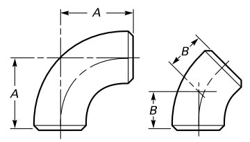
A mm inch |
B mm inch |
|---|---|---|---|
| 3/4 | 26.7 1.05 |
57 2.25 |
24 0.94 |
| 1 | 33.4 1.32 |
76 3.00 |
31 1.25 |
| 1-1/4 | 42.2 1.66 |
95 3.75 |
39 1.56 |
| 1-1/2 | 48.3 1.90 |
114 4.50 |
47 1.88 |
| 2 | 60.3 2.38 |
152 6.00 |
63 2.50 |
| 2-1/2 | 73.0 2.88 |
190 7.50 |
79 3.12 |
| 3 | 88.9 3.50 |
229 9.00 |
95 3.75 |
| 3-1/2 | 101.6 4.00 |
267 10.50 |
111 4.38 |
| 4 | 114.3 4.50 |
305 12.00 |
127 5.00 |
| 5 | 141.3 5.56 |
381 15.00 |
157 6.19 |
| 6 | 168.3 6.62 |
457 18.00 |
189 7.44 |
| 8 | 219.1 8.62 |
610 24.00 |
252 9.94 |
| 10 | 273.0 10.75 |
762 30.00 |
316 12.44 |
| 12 | 323.8 12.75 |
914 36.00 |
378 14.88 |
| 14 | 355.6 14.00 |
1067 42.00 |
441 17.38 |
| 16 | 406.4 16.00 |
1219 48.00 |
505 19.88 |
| 18 | 457.0 18.00 |
1372 54.00 |
568 22.38 |
| 20 | 508.0 20.00 |
1524 60.00 |
632 24.88 |
| 22 | 559.0 22.00 |
1676 66.00 |
694 27.31 |
| 24 | 610.0 24.00 |
1829 72.00 |
757 29.81 |
| 26 | 660.0 26.00 |
1981 78.00 |
821 32.31 |
| 28 | 711.0 28.00 |
2134 84.00 |
883 34.75 |
| 30 | 762.0 30.00 |
2286 90.00 |
946 37.25 |
| 32 | 813.0 32.00 |
2438 96.00 |
1010 39.75 |
| 34 | 864.0 34.00 |
2591 102.00 |
1073 42.25 |
| 36 | 914.0 36.00 |
2743 108.00 |
1135 44.69 |
| 38 | 965.0 38.00 |
2896 114.00 |
1200 47.25 |
| 40 | 1016.0 40.00 |
3048 120.00 |
1264 49.75 |
| 42 | 1067.0 42.00 |
3200 126.00 |
1326 52.19 |
| 44 | 1118.0 44.00 |
3353 132.00 |
1389 54.69 |
| 46 | 1168.0 46.00 |
3505 138.00 |
1453 57.19 |
| 48 | 1219.0 48.00 |
3658 144.00 |
1516 59.69 |
| Dimension | Tolerance | Description |
|---|---|---|
| Radius (R) | ±1% of specified radius | The bend radius should be within ±1% of the specified value. |
| Angle | ±1° of specified angle | The angle of the bend (e.g., 45°, 90°, 180°) should be within ±1° of the specified angle. |
| Length of Tangent (L) | ±5% of specified length | The length of the straight sections of pipe on either side should be within ±5% of the specified length. |
| Wall Thickness | ±12.5% of nominal thickness | The wall thickness variation should be within ±12.5% of the nominal thickness. |
| Straightness | ±1% of total length | The deviation from a straight line along the axis of the elbow should be within ±1% of the total length. |
| Ovality | ±1% of nominal diameter | The difference between the maximum and minimum outside diameters should not exceed ±1% of the nominal diameter. |